
Switch-Mode vs. Linear Power Supply
Amateur radio transceivers demand power supplies which have a large current capacity. The average 100 watt radio transceiver requires over 20 Amps when in transmit mode.
Overview
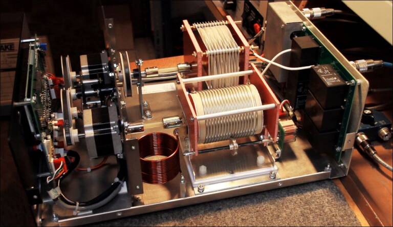
A linear power supply uses a large heavy transformer to step down the input high voltage AC to a level close to the desired output. From there, the low voltage AC is rectified to DC, smoothed and regulated,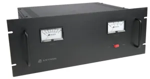 yielding the final output voltage.
A switch-mode (also known as switched-mode, switching mode, and switching) power supply, in its simplest form, takes the high voltage AC, rectifies it to DC, smooths it, then uses circuitry to switch the high voltage DC on and off at a high frequency in the primary of a much smaller transformer. Smaller transformers can be used because generally speaking (although not always), switching at a higher frequency increases the efficiency. From there, this switched waveform is rectified and smoothed. There is a feedback loop which controls the on/off time (duty cycle) of the high voltage switching. This is what sets the final desired output voltage.
On the surface, it’s all about trade-offs in price, size, efficiency, and weight, for a given output rating. Switching power supplies can often be 50-80% smaller for a given output rating.
For example, the Astron RM-60M, (top right) which supplies 50 amps continuous, 55 amps peak. This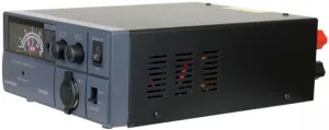 supply is 5 1/4 x 19 x 12 1/2 inches in size, and weighs in at a cool 60 lbs (27.2 kg). The retail price for this supply at the current time is $589.95.
Compare this with the TekPower TP50SW, (right) which supplies 50 amps (max). This supply is 14 x 10.1 x 5.8 inches in size, and weighs in at 6 lbs (2.7 kg). The retail price for this supply the current time is $159.99.
Switching at a higher frequency than 50/60 Hz brings you a ten-times reduction in weight, and almost a four-times reduction in price.
It’s a contentious subject, especially when it comes to amateur radio, mainly because of one word….
Noise
In the examples above, the Astron RM-60M boasts less than 5 mV of ripple at its rated current output, whereas the TekPower TP50SW spec is less than 100 mV of ripple. Switching power supplies generally have more output ripple and create more common mode noise than linear supplies, but how important is this to you in your application? What sort of device are you running which can’t handle 100 mV of ripple? What are the frequencies of this ripple and noise? Any decent ham radio worth its salt will have plenty of supply filtering in place to reduce ripple and noise. There will be chokes in there, capacitors with a low impedance at a wide range of frequencies, helping to lower the negative impact of this DC supply-borne noise.
Switched mode power supplies generate switching noise. This noise is often in the radio spectrum, and can contain discrete frequencies, harmonics, and broadband noise. It is generated primarily via the switched currents in the main switching devices. These switched currents are of a large magnitude, they change rapidly over very short time periods (di/dt), and unfortunately ringing and oscillations occur, which can be a main source of conducted and radiated RF and EM interference. Other sources of interference can include rectifier diode recovery, and input filter capacitors. Switching noise can be effectively reduced with careful design and PCB layout.
Switching supplies are also notorious for conducting noise onto the AC power supply line. I think this is partly due to a massive influx of cheaply made switching power supplies over the last couple of decades. I’m talking about things like cell phone & tablet chargers, laptop power supplies, battery chargers, and other small DC-powered appliances. The issue is one of cost – these things are manufactured by the million, and must be cheap. Cheap switching power supplies mean that not only does the line input and/or output filtering get slimmed down or removed, and the actual supply itself is made from minimal components, often due to size restrictions. See Ken Shirriff’s teardown blog post on the Apple iPhone charger for an example of such miniaturization. There is a link on that page also to a teardown of a cheap Chinese ripoff iPhone charger. Also see Dave from EEVBlog’s iPhone charger teardown video. The difference is startling. Also, while we’re on the subject of small, cheap Chinese switching supply teardowns, I highly recommend Big Clive and his YouTube channel for some fantastic teardowns of chargers, inverters, etc, some of which are incredibly crap, and/or dangerous.
We’ve established that switched mode power supplies generate switching noise, but they do have to comply with the standards in place (FCC, CISPR, etc). A well-designed, good quality switched mode supply will employ heavy line input filtering, preventing any noise generated from appearing back on the mains supply, allowing it to pass compliance testing, but also helping to prevent any similar noise currently on the AC supply from leaking into the switching supply. In a world full of bad quality switch mode supplies (such as detailed above), this is a good thing. On the other hand, generally speaking, line input filters are not used on linear power supplies. The only components the AC sees before it arrives at the transformer primary are maybe a fuse, a PTC, maybe some MOV’s… Depending on the reactance of the main transformer and other circuitry to the frequency of mains-borne interference, there may be little between it and your DC powered devices.
Either way, in the battle against interference, it is useful to acquaint yourself with the standards. This way, you can research any electrical device before purchase, and be confident of its performance as far as interference emission goes. However, in looking at FCC part 15, and EN55022 regulations, the first thing you’ll notice of interest (if you’re into amateur radio) is that there is apparently no restriction on radiated emissions below 30 MHz. Emissions testing below 30 MHz are focused on conducted emissions only.
With that in mind – what do the various regulations look like in regards to the amateur radio HF bands (1-30 MHz)?
FCC limits are expressed in μV, while CISPR/EN55022 limits are expressed in dBμV, so to avoid confusion, we’ll put them all in the same units: dBμV = 20Log(μV).
For example, in the 40 m band (~7 MHz):
FCC Class A limit is 3000 μV, FCC Class B is 250 μV.
CISPR/EN55022 Class A limit is 1000 μV, CISPR Class B is 316 μV (average).
You can see that the European EN55022 standard is more strict compared to the FCC part 15 limit when it comes to the less-restrictive Class A limit, and there’s really not much difference in Class B limits.
What is 316 μV anyway?? It’s nothing, right? Sure, it doesn’t sound like a lot, but if we convert 316 μV into dBm in a 50 ohm system, you’re looking at -57 dBm, which is somewhere between S9+10 dB and S9+20 dB on your S-meter.
Conclusion
Switched mode power supplies, if designed and made well, contain good shielding, aggressive line input filtering, snubber networks, other EMI/RFI countermeasures, and filtering which make them a totally viable alternative to very heavy and very expensive linear power supplies. Cheap, badly made switching supplies may eliminate some or all of the above in the interest of cost.
Arbitrarily labeling all switched mode power supplies as “bad”, or “noisy” and stonewalling on the subject doesn’t help. Do some research, and most of all – don’t buy a cheap/crap switched mode power supply and complain about noise. You get what you pay for.
A good switched mode power supply from a reputable company is going to be cheaper and lighter than a linear power supply from a reputable company of similar specification.
This article source is curtesy of Gordon W. Hudson – Ham Operator AD5GG – Website