

Antenna Tuners, Impedance Matching, and SWR
Antenna tuners seem to be some of the most misunderstood devices in all of amateur radio. In this article, I’ll try to explain what is happening when you use an antenna tuner. I’ll try not to get too much into mathematics, and I’ll also try to squash a few myths.
I really don’t like the name “antenna tuner.” It is a bit of a misnomer, because what most people are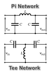 referring to is a box connected between their radio and antenna (or internal to their radio) which attempts to match the impedance of the antenna system to something close to the transceiver’s antenna port impedance. This is an impedance match, or impedance transformer. In a standard ham radio tuner, the circuits are essentially the same as those illustrated to the right. Either a Pi or Tee network is used, with the inductors and capacitors being variable via knobs and switches in a manual tuner, or different inductor and capacitor component values being switched in and out of the circuit via relays in the case of an automatic tuner.
Think about it–how can you tune an antenna, changing its electrical properties, by pressing a “TUNE” button on your radio? You can’t. With the exception of remote antenna feed point tuners, antenna tuners do not tune your antenna. They do not physically change your antenna system at all.
Antenna system impedance is composed of a resistive quantity, and a reactive quantity. The reactive quantity can be capacitive or inductive. If you’ve seen impedance written as 50+j17Ω, or 120-j45Ω, that’s what these are. Complex impedances in Cartesian (or rectangular) notation. The first example being 50 ohms resistive, with 17 ohms of inductive reactance (positive sign). The second example being 120 ohms resistive, with 45 ohms of capacitive reactance (negative sign).
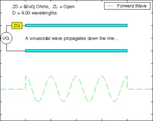 Complex test equipment often isn’t required to troubleshoot antenna impedance issues. Reactance causes phase shifts in voltage and current, resulting in some of the power delivered by your transceiver to be reflected, causing standing waves in the antenna feed line. The extreme example to the right shows 100% reflection due to no antenna connected to the transmitter. The ratio of the maximum amplitude of these standing waves to the minimum amplitude can be measured using a simple SWR meter. This indicates the level of impedance mismatch between the transceiver and the load.
A common misconception is that a high SWR due to a large impedance mismatch causes the power which is reflected back to its source to be absorbed by the transmitter output stage, overheating the output device (RF transistor finals, for example) and eventually burning them up. This is not the mechanism for failure during high SWR operation. When power is reflected and arrives back at the source, most of it is re-reflected back towards the load. This back and forth continues until the energy is dissipated in the load or via the feeder loss. You will often measure a higher output power on a power meter if the VSWR is high in your antenna system because some of the re-reflected power is added to the incident power and the total is displayed on the power meter.
Despite the huge focus placed upon it, and the never-ending quest for 1:1 VSWR, there is little real power loss associated with a moderate VSWR, and no real need for attaining the alleged gold standard of a 1:1 standing wave ratio from a power loss standpoint. In fact, a flat 1:1 VSWR over a wide frequency range can indicate a problem with your antenna system. I often run 800W into a 2:1 or 3:1 VSWR with no problems. Robust coaxial cable and antenna impedance transformers are required for this kind of operation. Check your coax and balun/unun specs.
In a system where there are impedance mismatches, the power loss and reflection routing can be visualized like this: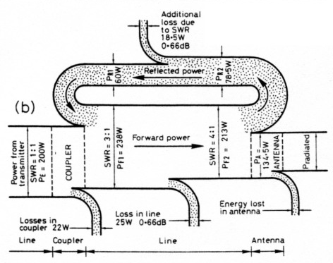
Damage to high SWR?
As mentioned previously, contrary to popular belief, failure from high VSWR is not due to the final output transistor (for example) absorbing reflected power.
Driving reactive loads is tough on electronics. High VSWR due to impedance mismatches shouldn’t be ignored. Impedance mismatches can cause failure of electronics, especially the output stages of RF amplifiers. This is due to the excessive reactance in the mismatched antenna system de-tuning the output stage and causing excessive current flow, or oscillation, or high voltages appearing at the output stage, pushing devices beyond their safe operating envelope.
Most modern transceivers will automatically reduce their output power as the VSWR exceeds 2:1 for their own protection, not because of reflected power, but because of the excessive reactance pushing the finals outside of their operating areas.
Tuner Location
Consider the diagram below. Point A is the transceiver antenna port. It is 50 ohms. Point B is the antenna tuner’s “to transceiver” port, which is also 50 ohms. The cable between Point A and Point B is also 50 ohms, and likely a short jumper. All good so far.
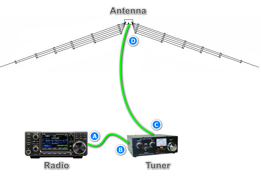
We know the antenna port at Point D is presenting an impedance mismatch, so what is happening between Points C and D? The cable between Point C and Point D is your main coaxial cable run to your antenna.
Impedance matching is achieved in the antenna tuner by presenting a complex conjugate impedance match at Point C. Essentially, the tuner is canceling out the reactive component of the complex impedance presented to it by the mismatched antenna system by presenting it with a reactive component of equal value, but opposite sign.
For example, to match a 50+j17Ω load to 50 ohms resistive, the antenna tuner would present a complex impedance of 50-j17Ω to the load (at Point C), canceling out the inductive reactance with capacitive reactance. Note: The complex conjugate match is only practical with lossless transmission lines. In reality you’ll never see a transmission line with zero loss. This is more theory than reality.
If the transceiver antenna port and the coaxial cable are both 50 ohms characteristic impedance, what happens if the antenna is not? It means that the coaxial cable is seen as part of the load, and the impedance measured will vary along the length of the coaxial cable feed line between Point C and Point D in the above diagram. The coaxial cable is acting as an impedance transformer (more on that later). The value of the impedance match needed will also vary depending on how long the coaxial cable between Point C and Point D is, or where in the coaxial cable the tuner is placed. Also, the measured SWR will decrease the longer the coaxial cable is, due to normal losses within the cable.
Tuner Location
So, you’re using a tuner to make your transceiver see close to a 50 ohm impedance. It is happy. All is well? Maybe not.
Considering the coaxial cable losses, and the fact that even when using a tuner between the radio and the coaxial cable antenna feeder, the SWR in the feeder will still be high, undue stress can be caused to the coaxial cable due to SWR-induced high voltage and current nodes within the cable. This effectively derates the coaxial cable power handling from a transmitter output power perspective.
How can you avoid this? Use two tuners to decouple the mismatch from the long antenna feed line?
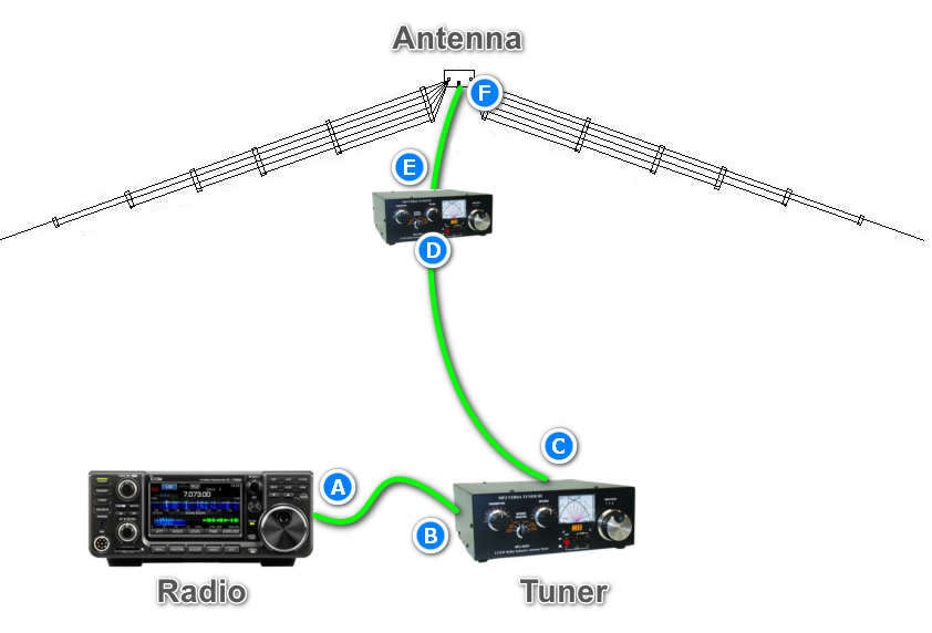
In the above diagram, the coaxial cable between Point C and Point D is your main run up to the antenna. The whole point of using two tuners is to shift the point of mismatch close to the antenna, instead of close to your radio. This way, the whole coaxial cable run up to your antenna is (practically speaking) at 50 ohms. The coaxial jumper between Point E and Point F can be kept as short as possible, keeping losses to a minimum.
Wait a minute – you really need two tuners? Absolutely not. This was just a step to illustrate where the inefficiencies lie.
Now lets reconsider the “Single Tuner” illustration above:
For the best efficiency, the long coaxial cable run should be from Point A to Point B, keeping the influence of the antenna impedance mismatch from affecting the coaxial cable feeder. This means the best place for an antenna tuner from an efficiency and low loss standpoint, is right at the antenna. Not at the transceiver.
Wait a minute – who wants to run out and adjust their tuner if it’s at the antenna feed point? Nobody does. You can have convenience, or efficiency. Not both.
A remote antenna tuner may inject some convenience into the equation, and work well for lower powers, but if you’re using 1500W, the amount of volt-amp reactive power the remote tuner will have to tune out may necessitate a huge device! Theoretically though, reactance consumes no power.
A perfect inductor stores energy in a magnetic field,
0.5∗𝐿∗(𝐼²)
A perfect capacitor stores energy in an electrostatic field,
0.5∗C∗(V²)
However, resistive losses are inevitable in the system, via inductor DC resistance, and capacitor equivalent series resistance, so power is consumed via that route.
In Summary
- Antenna Tuners do not physically tune antennas.
- Antenna Tuners are an impedance match circuit.
- Antenna Tuners match the impedance of your antenna system to the impedance of your transceiver.
- Antenna Tuners, the components in them, and your antenna system are all composed of reactive elements.
- Since reactance changes with frequency, a match is only perfect at one frequency.
- Changing frequency even slightly may require the match to be adjusted. This depends on the Q.
- If adjusted for an optimum impedance match, almost all of the power is transferred through the tuner. Power is not lost in the tuner, except for a small amount due to the efficiency of the circuit and associated components.
- Additional power is lost in the antenna system due to increased VSWR, but this is not usually significant. However, since the power is re-reflected over and over, it is subject to the coaxial cable losses over and over.
- When using a tuner, the impedance of the actual antenna system doesn’t change.
- Think about “non-natural” antennas such as 5/8λ verticals. These are not even close to 50 ohms, and will contain a matching circuit in the base of the antenna to bring it to 50 ohms. More or less, the same thing as an antenna base tuner does.
- A low VSWR does not guarantee your antenna is working well.
- A low VSWR does not necessarily indicate the antenna’s resonant point.
Yes a 2:1 VSWR reflects 11% of your power, but don’t lose sight of the fact that it’s re-reflected. It is not simply “lost” power. A common misconception is that this reflected power is gone. - A high VSWR derates the power handling capacity of your coaxial cable, since using an antenna tuner (on the radio side of your coaxial cable) does not remove the effects of a badly tuned antenna from your coaxial cable feeder.
- Long coaxial cables can mask the effects of a badly tuned antenna.